PLASTICS TANKS, REESERVOIRS AND VESSELS FOR WASTE WATER TREATMENT PLANTS AND DEVICES

Krušik Plastika a.d. has been manufacturing these types of tanks and vessels from the very beginning of application of waste water treatment plants in this region.

Our plastics tanks and vessels, when considering their characteristics such as resistance to chemical and atmospheric influences, longevity and health-influence safety, are ideal for purpose of waste water treatment, i.e. for devices such as: mineral oil separators, fat separtors, bioligical and chemical waste water treatment plants, biological sewage cesspools, etc.

    The quality and the reliability of the products of Krušik Plastika a.d. have been recognized by the company Ekolog doo Beograd, founded in 1991, a pioneer in applications of waste water treatment technology in the region of former Yugoslavia. This has resulted in cooperation of the two companies, exchange of know-how, and the generating of joint products such as:

    • oil water separators,
    • grease separators, and
    • waste water treatment plants – “BIO-PUR”.
    bio pur otvoren
    bio pur unutrašnjost

    Oil water separators

    Oil water separators are used for purification of waste waters either from rainfall ducts (for surfaces subjected to percipitation such as: traffic roads, town squares, parking lots), or from objects such as petrol stations, car mechanics workshops, garages, industrial plants, etc.

    separatori ulja i naftnih derivata

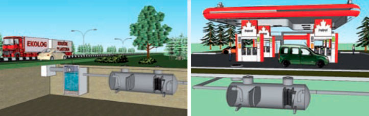
    Rainwater, contaminated with mineral oil, diesel or gasoline, after passing through Krušik Plastika a.d. oil separator, becomes clean enough to meet law regulations regarding environmental safety, so that it is safe to let it flow into a natural recipient or public sewage system.

    Our oil water separators are designed and manufactured in accordance with EN 858: “Separator systems for light liquids (e.g. oil and petrol)”.

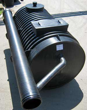
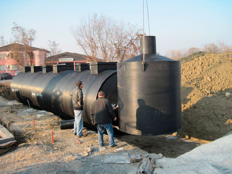
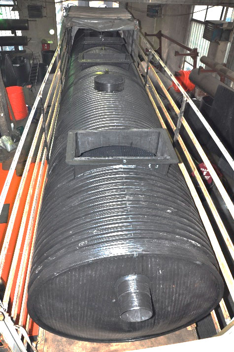
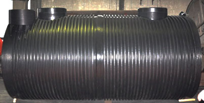
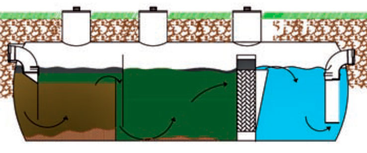
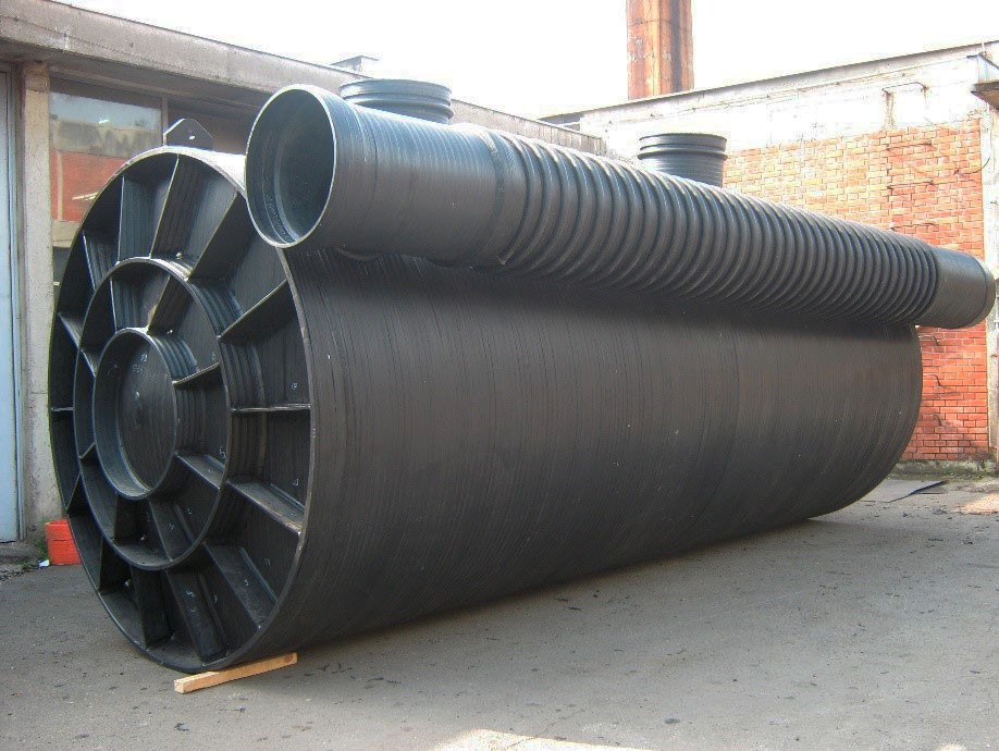
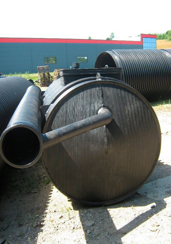
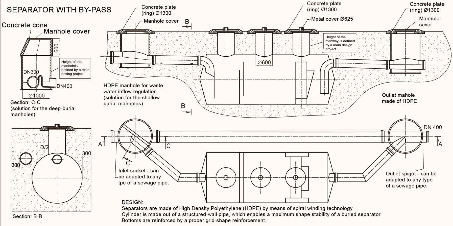
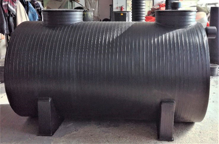
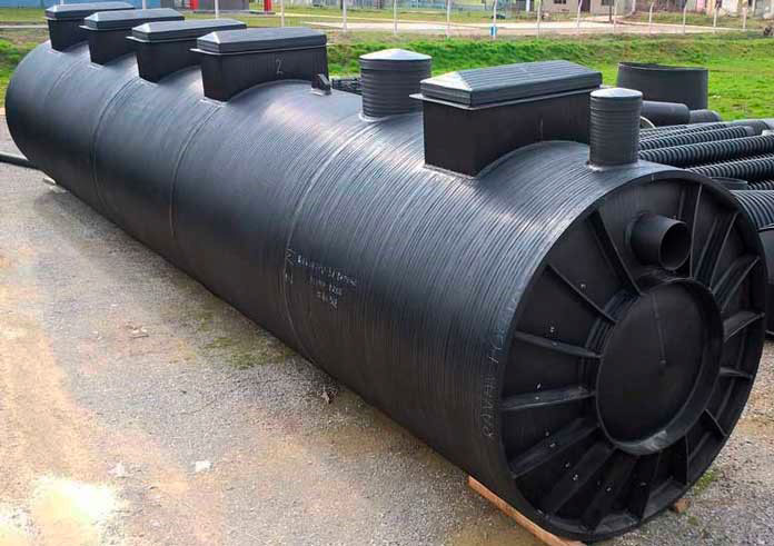
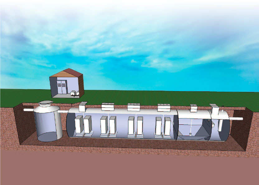
    In terms of construction, Krušik Plastika a.d. oil water separtors are very similar to our horizontal tanks – type C, and they consist of: sedimentation chamber, middle chamber with a coalescing filter, outlet chamber (beyond the coalescing filter) and a reservoir for the separated oil.

    Each sedimentation chamber is equipped with the proper elements for directing of flow and for prevention of swirling of water (water vortex). By this, sedimentation of solid particles is intensified, and an undisturbed and smooth separation of oil particles during the next steps of purification is enhanced.

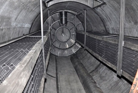
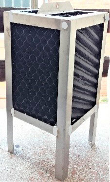
    The role of the coalescing filter is to remove the smallest drops of oil out of water that is contaminated by oil or petrol. The coalescing filter is made of so called “oleophilic” materials, whose important characteristic is the fact that drops of oil adhere (stick) to it. As soon as a drop of oil, as a particle which float through water, touch the surface of the “oleophilic” coalescing filter, it becomes separated from the water. Oil drops, separated from water and adhered to the coalescing filter, merge together into a bigger oil drops, i.e. some kind of coalescence of oil drops occurs. This way, a large number of smaller oil drops forms a smaller number of bigger oil drops, which, according to Stokes Law, due to gravity action, float to the surface more easily, and they are being separated into the “separated oil reservoir” of the oil water separator.

    separatori ulja i naftnih derivata
    separator ulja i naftnih derivata
    koalescentni filter

    Function and maintenance

    After placement, the device needs to be filled with water up to the output level and hydraulic flow of water should be checked.

    Depending on the duration of work, amount and level of contamination of input water, it is needed to provide, at a certain period of time, transportation of precipitated solids from sedimentation tank and separated oil and to ensure their safe disposal in accordance with regulations for hazardous waste disposal.

    Installation

    Installation is quick and easy. There are no additional costs for concrete works, making of foundation, etc. A separator is installed in a trench, in stable or stabilized soil, and must be placed onto a dense sand or gravel bedding which must be 300 mm high.

    Backfilling of the separator must be performed evenly, by pouring and compacting sand (or gravel) all around the perimeter of the separator. Compaction is done manually or by proper soil compaction eqipment (rammers, vibrating plate compactors, vibro tampers…) and in this process it is necessary to be careful so that you do not damage the bottom or the boddy of the separator.

    Material for backfilling is used up to 200 mm above the vertex (the crown) of the separator, and for remaining filling the material from excavation can be used.

    More detailed explanation of the process of installation and backfilling is explained in the norm EN1610. In case of separator installation into the soil with groundwater, pay attention to occurrence of uplift forces (buoyant forces).

    Separators with BYPASS

    A special sub-type of separator for mineral oils and petroleum derivatives, produced by Krušik Plastika A.D. are the so-called “Separators with BYPASS”, which are also defined by the EN 858 standard.

    They are used for the treatment of storm waters from large surfaces (roads, parking lots, squares…) where occurrence of a discontinuous flow is possible. Using of such a separator ensures that the first wave of contaminated water flows into the separator, while the remaining storm water, from surface area, is flowing through the bypass.

    This way, an optimization of the device capacity is achieved, while the total investment is significantly reduced.

    This is a classical system for separators installation with an external bypass between two manholes. Receiving manhole has special construction which provides dividing and drainage of water into the separator and bypass.

    Plastični separator sa bajpasom
    Plastični separator sa bajpasom

    Installation in case of high level of ground water – “anchoring”

    In such cases, a reinforced concrete plate (ferroconcrete) must be done on the trench bottom, instead of the sand bedding, and the separator must be fixed to this plate by means of proper anchors (anchor bolts, rebar, etc.), in order to prevent its buoancy (floating towards the surface). Dimensions of the concrete plate are determined on the basis of the actual buoyant force (uplift force). The number of anchors required, as well as the necessary strength of fixing straps are defined on the basis of the active forces.

    *) Dimensions of oil separators “L” and “D” represents inner diameter and length, respectively, analogous to the tanks of type “C”.

    Oil water separators for nominal flows (nominal sizes) different from the standard ones listed in the table, can be manufactured upon request.

    Grease separators

    Grease separators (fat separators) are devices for treatment of waters that contain greases (fat) of animal or vegetable origin. In terms of design and function they are similar to oil water separators. Specifically, they operate on the same principle, but they are intended for separating of grease particles from waste waters generated due to food preparation (kitchens, restaurants, cook shops, eateries, diners…), but also of those generated by the food industy plants (butcheries, slaughterhouses, cheese dairies, plants for production of vegetable fats or butter, fish processing plants, etc). They are not intended for grease separation neither from water that contains greases of mineral origin, nor from water that contains stable emulsions of oil or grease of any origin.

    Grease separators are usually installed as close as possible to the place where wastewater flows out of the building, and their primary function is a proper degreasing of the water in order to prevent grease particles to be sticked to walls of drain (sewage) pipes, i.e. to prevent reducing of flow cappacity or even plugging of the drain pipeline. The environmental protection is, of course, an important puprose for their usage as well.

    Our plastics grease separtors are designed and manufactured in accordance with European norms EN1825-1: “Grease separators. Principles of design, performance and testing, marking and quality control”, and EN1825-2: “Grease separators. Selection of nominal size, installation, operation and maintenance”.

    Selection of a nominal size of a separator (NS) is usually carried out on the basis of a design project, where an actual intensity of flow (in lit./sec.) is defined, and the selected nominal size of the separator must be greater or equal to the designed one. If this value is not known, then the nominal size slection is carried out either on the basis of nominal number of meals and a type of a kitchen, or on the basis of the dish-washing equipment installed in the kitchen.

    separator kuhinjskih masti

    Grease separators for nominal flows (nominal sizes – NS) different from the standard ones listed in the table, can be manufactured upon request.

    Grease separartors can be either a vertical or horizontal type.

    Waste water treatment devices BIO-PUR

    Waste water treatment device (Bio-Pur) is an ideal solution for application in zones, places or parts of settlements that are located far from urban infrastructure and sewage networks, so that water can be discharged into natural recipient.

    Bio-pur is suitable for households, cottages, campsites, hotels, restaurants, schools, factories, villages, small settlements, etc.

    BIO PUR device works on the principle of biodegradation using “floating bed” technology. Water flow through the device is gravitational, without use of pumps or any moving elements. Using this method, water flowing back into the facility is prevented in case of power failure.

    Waste water from facilities enters the first part of BIO PUR plant in which preliminary deposition and separation of bulky waste is performed, so that such kind of material could not pass through other phases of purification. The next phase of treatment is biological degradation of organic substances, based on deep aeration system. This phase is intensified with “floating bed” system with floating biofilm carriers. The next phase of treatment is aerobic stabilization and deposition of mineralized sludge. Active sludge from this phase is mixed with deposited material from the phase of preliminary deposition, which prevents appearance of unpleasant odour. Finally, purified and clarified water overfalls into last chamber where the two last phases of treatment are performed: filtrational absorption and disinfection.

    Water purified with this method is of a high quality, and can be discharged into open watercourse.

    Burying procedure:

    BIO PUR is to be burried into a proper trench, analogous to the burial procedure of our horizontal tanks – type C. Concretely, it is placed onto a 300 mm high, well compacted, sand or gravel bedding. Backfilling is also performed by using clean, well-graded sand or gravel, with no sharp particles. Both filling (embanking) and compacting of the backfill is to be performed layer by layer, with the layers of thickness of 200 mm, uniformly all around the perimeter of the casing of the device. Care must be taken in order not to damage the cylinder or the bottoms of the device during compacting of the backfill.

    After reaching the highest point of the cylinder (the body) of the device, the device is to be covered with the last layer of sand (or gravel), 200mm thick, and the rest of the trench is to be filled by using the escavated earth, but without big and sharp particles that may reach the device. If a device is to be installed at a place where the ground water level is so high that it may reach the device, the uplift forces (buoyant forces) must be taken into account. In cases of special burial conditions, or in the case of devices of a vertical type, the device is to be placed on a flat, horizontal concrete plate.

    The sludge, generated inside the device, must be evacuated on a regular basis, and its disposal must be carried out in accordance with the proper law regulations. After installing, each BIO-PUR device must be completely filled with water and also it must be checked whether the water flow through the device is unobstructed.

    NEED MORE INFO?

    Check out our contact page